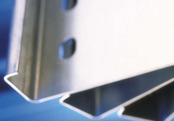
Cold-formed construction profiles of the Z, C, Σ and U types are made of cold-rolled steel.
Cold-rolled sections are a proven and effective construction solution. Our company’s basic offer in this area consists of sections (purlins) with Z , C, Σ and U profiles . Additionally, thanks to the launch of a new production line, we have expanded our offer to include C+ and Σ+ profiles . The cold-formed C-type profile is a classic solution that offers a favorable combination of cost effectiveness while maintaining the desired load-bearing parameters. Additionally, its universal shape facilitates installation and use in various configurations. Moreover, it can be produced from a wide range of feed tapes, as well as various thicknesses of the sheet metal itself, up to 3.5 mm – which gives a lot of possibilities that will easily meet any architectural requirement.
A wide variety of strength parameters of sections allows for optimal selection of the amount of material needed – we encourage you to familiarize yourself with the full offer of our cold-rolled sections

Metallic coatings –
Technical details and parameters of cold-formed sections type C. They are made of high-quality S350 GD or S390 GD steel (on request). Universal and specially developed bends offer high load-bearing parameters and at the same time offer a wide range of applications.
Dimension C for Z and C profiles can be made in lengths from 16 to 30 mm. The exceptions are profiles with a height of H = 100 and the Σ profile – in this case, dimension C is always 16 mm.
NOTE C-profile purlins can use sheet metal up to 3.5 mm thick (after consultation with the sales department). Variant with “whiskers” – C+ type section, can use sheet metal up to a maximum thickness of 2.5 mm

| PROFILE C | thickness | Libra | H | B | C |
| mm | kg/m | mm | mm | mm | |
| C 100 | 1.50 | 2.64 | 100 | 48 | 16 |
| 2.00 | 3.52 | 100 | 48 | 16 | |
| 2.50 | 4.36 | 100 | 48 | 16 | |
| 3.00 | 5.23 | 100 | 48 | 16 | |
| 3.50* | 6.10 | 100 | 48 | 16 | |
| C 100 | 1.50 | 2.88 | 100 | 60 | 16 |
| 2.00 | 3.84 | 100 | 60 | 16 | |
| 2.50 | 4.76 | 100 | 60 | 16 | |
| 3.00 | 5.71 | 100 | 60 | 16 | |
| 3.50* | 6.66 | 100 | 60 | 16 | |
| C 150 | 1.50 | 3.24 | 150 | 48 | 21 |
| 2.00 | 4.32 | 150 | 48 | 21 | |
| 2.50 | 5.36 | 150 | 48 | 21 | |
| 3.00 | 6.43 | 150 | 48 | 21 | |
| 3.50* | 7.50 | 150 | 48 | 21 | |
| C 150 | 1.50 | 3.60 | 150 | 60 | 21 |
| 2.00 | 4.80 | 150 | 60 | 21 | |
| 2.50 | 5.96 | 150 | 60 | 21 | |
| 3.00 | 7.15 | 150 | 60 | 21 | |
| 3.50* | 8.34 | 150 | 60 | 21 | |
| C200 | 1.50 | 3.84 | 200 | 48 | 21 |
| 2.00 | 5.12 | 200 | 48 | 21 | |
| 2.50 | 6.36 | 200 | 48 | 21 | |
| 3.00 | 7.63 | 200 | 48 | 21 | |
| 3.50* | 8.90 | 200 | 48 | 21 | |
| C200 | 1.50 | 4.20 | 200 | 60 | 21 |
| 2.00 | 5.60 | 200 | 60 | 21 | |
| 2.50 | 6.96 | 200 | 60 | 21 | |
| 3.00 | 8.35 | 200 | 60 | 21 | |
| 3.50* | 9.74 | 200 | 60 | 21 | |
| C 250 | 1.50 | 4.50 | 250 | 48 | 21 |
| 2.00 | 6.00 | 250 | 48 | 21 | |
| 2.50 | 7.40 | 250 | 48 | 21 | |
| 3.00 | 8.88 | 250 | 48 | 21 | |
| 3.50* | 10.36 | 250 | 48 | 21 | |
| C 250 | 1.50 | 4.80 | 250 | 60 | 21 |
| 2.00 | 6.40 | 250 | 60 | 21 | |
| 2.50 | 7.96 | 250 | 60 | 21 | |
| 3.00 | 9.55 | 250 | 60 | 21 | |
| 3.50* | 11.14 | 250 | 60 | 21 | |
| C 300 | 1.50 | 5.02 | 300 | 48 | 21 |
| 2.00 | 6.69 | 300 | 48 | 21 | |
| 2.50 | 8.28 | 300 | 48 | 21 | |
| 3.00 | 9.94 | 300 | 48 | 21 | |
| 3.50* | 11.60 | 300 | 48 | 21 | |
| C 300 | 1.50 | 5.33 | 300 | 60 | 21 |
| 2.00 | 7.10 | 300 | 60 | 21 | |
| 2.50 | 8.72 | 300 | 60 | 21 | |
| 3.00 | 10.46 | 300 | 60 | 21 | |
| 3.50* | 12.20 | 300 | 60 | 21 | |
| C 350 | 1.50 | 6.26 | 350 | 75 | 21 |
| 2.00 | 8.35 | 350 | 75 | 21 | |
| 2.50 | 10.40 | 350 | 75 | 21 | |
| 3.00 | 12.48 | 350 | 75 | 21 | |
| 3.50* | 14.56 | 350 | 75 | 21 | |
| C 400 | 2.50 | 11.32 | 400 | 75 | 21 |
| 3.00 | 13.58 | 400 | 75 | 21 | |
| 3.50* | 15.84 | 400 | 75 | 21 | |
“Z” and “C” profiles enable quick and easy development of industrial or service halls. They are connected mainly with screws. For this purpose, three types of holes are provided in the profiles (table 1):
Table 1.
| Round holes (diameter – Ø in mm) | Bean holes (length x width – in mm) |
|
|
|
|
|
|
| |
| |
|
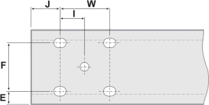
Depending on the type of profile used, there are different values for the spacing of technical and assembly holes. Their values are given in the table below.
The drawing shows the possibilities of longitudinal drilling.
Opening is possible in all planes of the section.

E – dimension from the wide shelf Bg (for Z-type profiles)
Hole arrangement
| C profile | sheet thickness | E | F |
|---|---|---|---|
| mm | mm | mm | |
| C 100 | 1.5 | 25.0 | 50 |
| 2 | 25.0 | 50 | |
| 2.5 | 25.0 | 50 | |
| 3 | 25.0 | 50 | |
| C 150 | 1.5 | 50.0 | 50 |
| 2 | 50.0 | 50 | |
| 2.5 | 50.0 | 50 | |
| 3 | 50.0 | 50 | |
| C200 | 1.5 | 50.0 | 100 |
| 2 | 50.0 | 100 | |
| 2.5 | 50.0 | 100 | |
| 3 | 50.0 | 100 | |
| C 250 | 1.5 | 50.0 | 150 |
| 2 | 50.0 | 150 | |
| 2.5 | 50.0 | 150 | |
| 3 | 50.0 | 150 | |
| C 280 | 1.5 | 50.0 | 180 |
| 2 | 50.0 | 180 | |
| 2.5 | 50.0 | 180 | |
| 3 | 50.0 | 180 | |
| C 300 | 1.5 | 50.0 | 200 |
| 2 | 50.0 | 200 | |
| 2.5 | 50.0 | 200 | |
| 3 | 50.0 | 200 | |
| C 350 | 1.5 | 50.0 | 250 |
| 2 | 50.0 | 250 | |
| 2.5 | 50.0 | 250 | |
| 3 | 50.0 | 250 | |
| C 400 | 1.5 | 50.0 | 300 |
| 2 | 50.0 | 300 | |
| 2.5 | 50.0 | 300 | |
| 3 | 50.0 | 300 | |
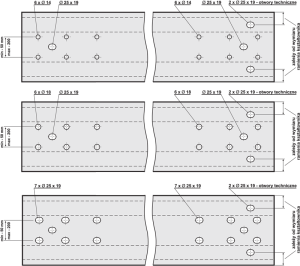
The types and arrangement of holes in Z/C sections are basically any and we present them in sample drawings.

Types and arrangement of holes – c profile

help@factorymarket.online

Parnu Savi 3/2 80040
